Author: Site Editor Publish Time: 2021-02-24 Origin: Site


In the process of designing and constructing digital system equipment for radio and television, more energy is often invested in selecting more suitable equipment, but the selection of cables for connecting equipment is also a key part. Once you choose the wrong cable, you will pay the same price as the wrong device. Choosing the correct cable and standardized installation must be based on a comprehensive understanding of relevant standards and cable characteristics. This article mainly introduces digital audio and video standards, typical cable characteristics, and cable transmission applications in digital systems.
Digitally process and transform the audio signal that is analog, and specify the transmission format and standard. The Acoustic Engineering Society of America and the European Broadcasting Union (AES/EBU) have jointly developed digital audio standards. The two key parameters related to cables in this standard are code rate and characteristic impedance: at the recommended 48 kHz audio sampling frequency, the code rate is 3.072 Mb/s. The structural characteristic impedance of the twisted pair is 110Ω±20%, and the characteristic impedance of the coaxial cable is 75Ω.
The Society of Motion Picture and Television Engineers (SMPTE) has developed a serial digital transmission standard: SMPTE259M. SMPTE259M proposes the main indicators of transmission as follows: Peak-to-peak data stream level: 800 mV±10%. Rise and fall time: 0.4~1.5 ns. Overshoot: ±10%. For 4:2:2 digital components, the code rate is 270 Mb/s, and the jitter is less than 740 ps.

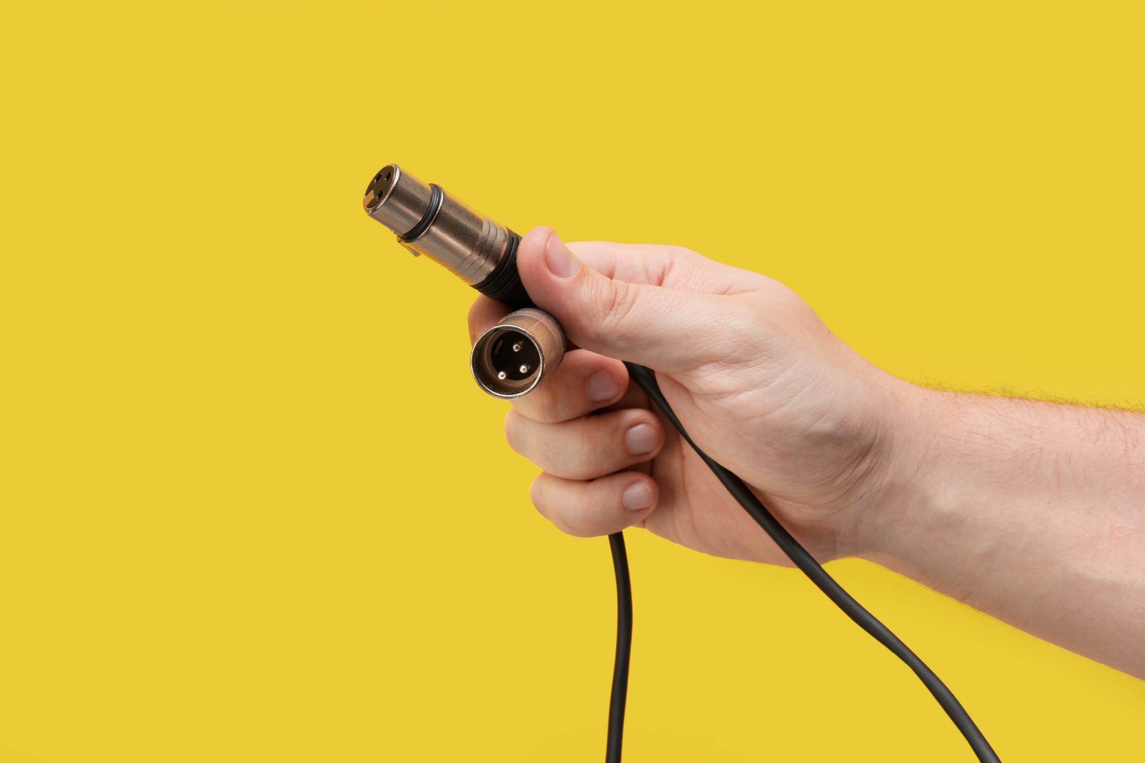
Due to the wide impedance range of the AES/EBU standard, the characteristic impedance of the twisted-pair shielded cable can range from 88 to 132Ω, with 110Ω being the most ideal. Twisted pair cables should be shielded. If it is a multi-pair cable, each pair of wires should be individually shielded. Foil shielding is recommended for permanent installations, while foil shielding with mesh shielding is recommended for bending applications. A pair of wires can transmit two channels of digital audio. The cable can be terminated with an XLR connector, can also be perforated, or soldered to a jumper board. Most digital audio cables use foamed polyethylene to minimize the size. Standard foamed polyethylene is easy to squeeze, which may cause changes in characteristic impedance. The cable manufacturer uses a special foamed high-density polyethylene, which greatly improves impact resistance compared with standard foamed insulators.
Twisted-pair shielded cable is one of the earliest used means of transmitting analog audio signals. Its advantages are: it is easier to lay when the transmission distance is short, compared with other transmission means, the investment is relatively small, the technology is more mature, and the maintenance is convenient. The disadvantage is that the frequency response is poor when the transmission distance is long. AES3 stipulates the transmission standard of digital audio within 100 m. The signal source and load impedance should be 110Ω. Because the frequency of AES/EBU digital audio is as high as 6 MHz, capacitance and high-frequency loss will cause high-frequency drops. Finally, the edges of the signal become rounded and the amplitude is reduced so that the receiver cannot recognize "1" and "0". Therefore, 110 Ω balanced transmission is used within 100 m, and unbalanced coaxial cable transmission with an impedance of 75 Ω is used for transmission above 100 m.
There are a wide variety of plugs that can be used on audio cables, from RCA to professional XLR. Therefore, when people start to consider the transmission of professional digital audio signals, they naturally think of using this twisted-pair shielded cable with XLR plugs. Both AES and EBU are working on the standardization of digital audio signal transmission. The two organizations work closely together and have similar standards. The broadcasting industry uses the AES/EBU interface standard. AES3-1992 and its predecessor AES3-1985 standard typically use twisted-pair shielded cable and XLR plugs.

If through some method the level of the AES digital audio signal can be changed to 1 V and the impedance becomes unbalanced 75Ω, then the digital audio signal can be transmitted like a video signal. Signals with a bandwidth of 3 to 10 MHz can be well-matched with current analog video amplifiers and matrix switches. The AES3-ID standard includes information about cables, cable equalizers, and receiver circuits. The receiver also includes converters that convert AES3 equipment and cable systems.
According to the AES3-ID standard, it can be connected with the XLR plug on the traditional digital audio equipment through an external converter. The converter can reduce the voltage to 1 Vp-p, and use an impedance matcher to convert 110Ω to 75Ω. When the receiver needs to be restored to its original state, it can convert 75Ω to 110Ω. Many coaxial cable manufacturers can provide such converters.
Digital audio equipment manufacturers hope to produce an interface that goes beyond XLR plugs and is directly compatible with 75Ω coaxial cables and analog video equipment. The American Society of Motion Picture and Television Engineers (SMPTE) established the standard as ANSI/SMPTE276M. The standard includes a point-to-point coaxial cable interface to transmit AES/EBU digital audio signals to ensure that a certain degree of compatibility is maintained between digital audio and video coaxial cables and TV equipment interfaces in TV applications. It does not prevent the use of twisted-pair shielded cables to transmit balanced AES/EBU audio signals on these devices, because these two transmissions can be connected through a matching network. But the data encoding of the transmission channel should adopt ANSI4.40-1992 (AES-3-1992) standard. It is said that Japan’s Tokyo Broadcasting System (TBS) was tested on 110Ω input/output impedance equipment. When a 75Ω coaxial cable is used, the stable transmission distance can reach 500 m. The transmission of AES-3 format digital audio signals through coaxial cables also provides new application prospects for the currently used analog video equipment, such as analog video amplifiers and line matrix switches.
Usually, the digital audio signal is inserted (embedded) into the digital video signal, that is, the digital audio signal is inserted into the line and field synchronization pulse (line and field blanking) period of the video signal, so as to be transmitted simultaneously with the digital component video signal.
In many TV coaxial cable applications, the digital audio signal is embedded in the digital video signal, transmitted on a coaxial cable, and then the digital audio signal is de-embedded from the video signal (separation multiplexing technology) and runs independently inside the device. For example, in the field of broadcasting, there are very few cases of video and audio segmentation. The use of embedded audio technology can reduce the matrix by one level, and the connection is simpler. In particular, DVCPRO and other format signal source devices have embedded audio SDI interfaces, making this application more practical.

Precision analog video cables mostly use double-layer mesh shielding and have a very low loss in the frequency range from very low frequencies (close to DC) to about 10 MHz, but they are not optimal for high frequencies of digital signals.
The new coaxial cable structure specially designed by coaxial cable suppliers for digital transmission uses several design parameters. It has the precise electrical characteristics required for high-frequency transmission and has better performance than the original design. The choice of solid bare copper for the center conductor has better characteristic impedance stability and reflection loss (SRL). Digital signal transmission includes low-frequency transmission along the center of the conductor and high-frequency transmission along the outer surface of the conductor due to the skin effect. For these reasons, pure copper conductors without coating have the best performance.
The dielectric material (insulating material) is made of high-density foamed polyethylene. The special design has impact resistance and can prevent the conductor from moving. Impact and conductor movement will cause the characteristic impedance to change. Gas injection technology can generate very uniform foam and increase the propagation speed (82-84%). Keeping the rate constant can minimize synchronization problems between cables.
Precision analog cables are very effective with only double-layer mesh shielding, but they are not the best choice for digital signals. Mesh shielding is ideal for frequencies below 10 Hz, and foil shielding is the best for high frequencies. Since the digital signal transmission contains two frequencies, a foil layer and mesh design are used.
In serial digital systems, the data rate to be transmitted is as high as 270 Mb/s or 360 Mb/s. In such a high-frequency range, the loss of a precision analog video cable will still increase significantly. Although serial digital signals can easily overcome these effects through equalization, the transmission distance will be significantly reduced. Therefore, it is only feasible to use cables with existing quality standards in digital systems under short distances.
TV coaxial cable manufacturers specifically design new, low-loss, foam-type dielectric cables for serial digital signals. For example, the Hongsen video coaxial cable, which is used for replacement, is thinner but more flexible, and the price is cheaper than 8281. However, it has more excellent characteristics in the frequency band area related to serial digital signals. It can be used in fixed installation and long distances, but different BNC connectors must be used. In addition, the foam core may deform when compressed, resulting in reflections.

Analog cables can be used for digital audio signal transmission, but only for distances of about 15 m. The exact length is determined by the error correction performance and the signal instability tolerance of the receiver. The characteristic impedance of most analog cables is 40~70Ω. Mismatch with the characteristic impedance of the nominal 110Ω will cause signal reflection and instability, resulting in receiver code errors. In addition, the high capacitance of the analog cable will greatly reduce the rise time of the digital square wave.
When digital cables are used for analog signal transmission, they are superior to analog cables because of their extremely low capacitance. When transmitting audio signals, it can transmit 30% longer than the same type of analog audio cable under the same attenuation.
Among analog video cables, only precision video cables can be used for digital signal transmission. Standard video cables can be multi-stranded center conductors or copper-clad steel conductors. They may not have sufficient shielding capabilities as described above, can only transmit a short distance, and have a high bit error rate. Standard video cables are usually not tested for SRL. Beware of hidden dangers caused by the use of ordinary coaxial cables to transmit digital signals.
Digital cables can be used for analog signal transmission, but the analog equipment must include a cable equalizer, which is used within the loss characteristics of a specific cable. If the transmission distance is short, there may be no need to consider equalization issues. Many equipment manufacturers produce equalization cards specifically for new digital cables.
It is possible to mix foam and solid polyethylene designs in the same transmission, but correct compensation calculations must be made based on the delays of these two cables. The time delay of the foam core cable is 1.24 ns/ft, while the time delay of the solid polyethylene is 1.54 ns/ft. The loss characteristics of cables are also different. If cable types are mixed, both parameters must be considered. Based on experience, it is best to use the same design from beginning to end.

The digitization of audio and video signals has improved the application consistency of data cable technology, which uses unshielded twisted pair cables (UTP). Almost all UTP cables can support low-bandwidth or low-speed applications, and there are few cables that can transmit digital video signals like 270 Mb/s over a considerable distance. For example, the problem of coaxial cable lies in bandwidth (frequency) or speed and transmission distance. The key issue is distance. The stability of the UTP cable determines its transmission distance. The physical concentricity, the positional relationship between the conductor and the conductor, the wire pair and the wire pair, and the maintenance condition along the entire cable length will determine the transmission length that does not exceed the tolerance at the specified frequency. The quality of the cable will determine the signal quality within a certain distance.
The multimedia twisted pair cable is a 4-pair, characteristic impedance 100Ω, 24AWG UTP cable. The conductors of each pair are glued together and maintain a stable position and direction during the installation process, regardless of the degree of bending and the accuracy of the installation. Therefore, the wire pair must be divided when it is terminated. The wire pairs are precisely positioned in their respective channels so that they can also maintain their own direction. The crimping block and all other hardware must have a specific characteristic impedance (100Ω) to obtain the best performance.
The video standard applies to unbalanced signals transmitted via coaxial cables. Multimedia twisted-pair cables and other UTP cables need a balun. The balun converts the unbalanced 75Ω video signal into a 100Ω balanced transmission and then restores it to a 75Ω unbalanced signal.
Multimedia twisted-pair cables can transmit different types of signals in each pair. When UTP is used for audio, video, or data mixed transmission, it is called a "sheath sharing" application, and more and more engineers and technicians are considering the use of multimedia cables.
Hongsen is a professional manufacturer and supplier of coaxial cable in China, we can manufacture tv coaxial cable, rf coaxial cable, flexible coaxial cable, mini coaxial cable, rg6 coaxial cable, rg59 coaxial cable, rg11 coaxial cable, rg174 coaxial cable, rg8 coaxial cable, etc. Contact us for more details now.
PVC vs FEP Hook Up Wire: Which Insulation Material Is Right for Your Project?
Selection and Applications between 20 vs 18 vs 16 Gauge High Temperature Wire
Which One Is Better Solid Hook Up Wire vs Stranded Hook Up Wire?
Which Insulation Material Is Used for High Temperature Wire?
Why PTFE Hook-Up Wire Excels in Chemical Processing and Medical Devices
The Complete Guide to Hook-Up Wire Types: Materials, Ratings, and Applications
Top 5 Benefits of Using FEP Hook-up Wire in Industrial Applications
FEP vs PTFE Hook-up Wire: What’s the Difference and Which One Do You Need?
|Copyright 2002-2019 Hangzhou Hongsen Cable Co., Ltd. All Rights Reserved. Coaxial Cable Manufacturer
Powered by hi-eweb.com | Sitemap | XML
