Author: Site Editor Publish Time: 2026-11-02 Origin: Site


RG142 uses a solid center conductor; RG400 uses a stranded center conductor. This is the main difference behind their handling characteristics. RG400 is generally easier to route around components, while RG142 suits fixed connections where its stiffer construction fits the installation.
This guide compares their construction, explains how the differences affect installation, and helps you decide what to check before choosing or replacing either cable.
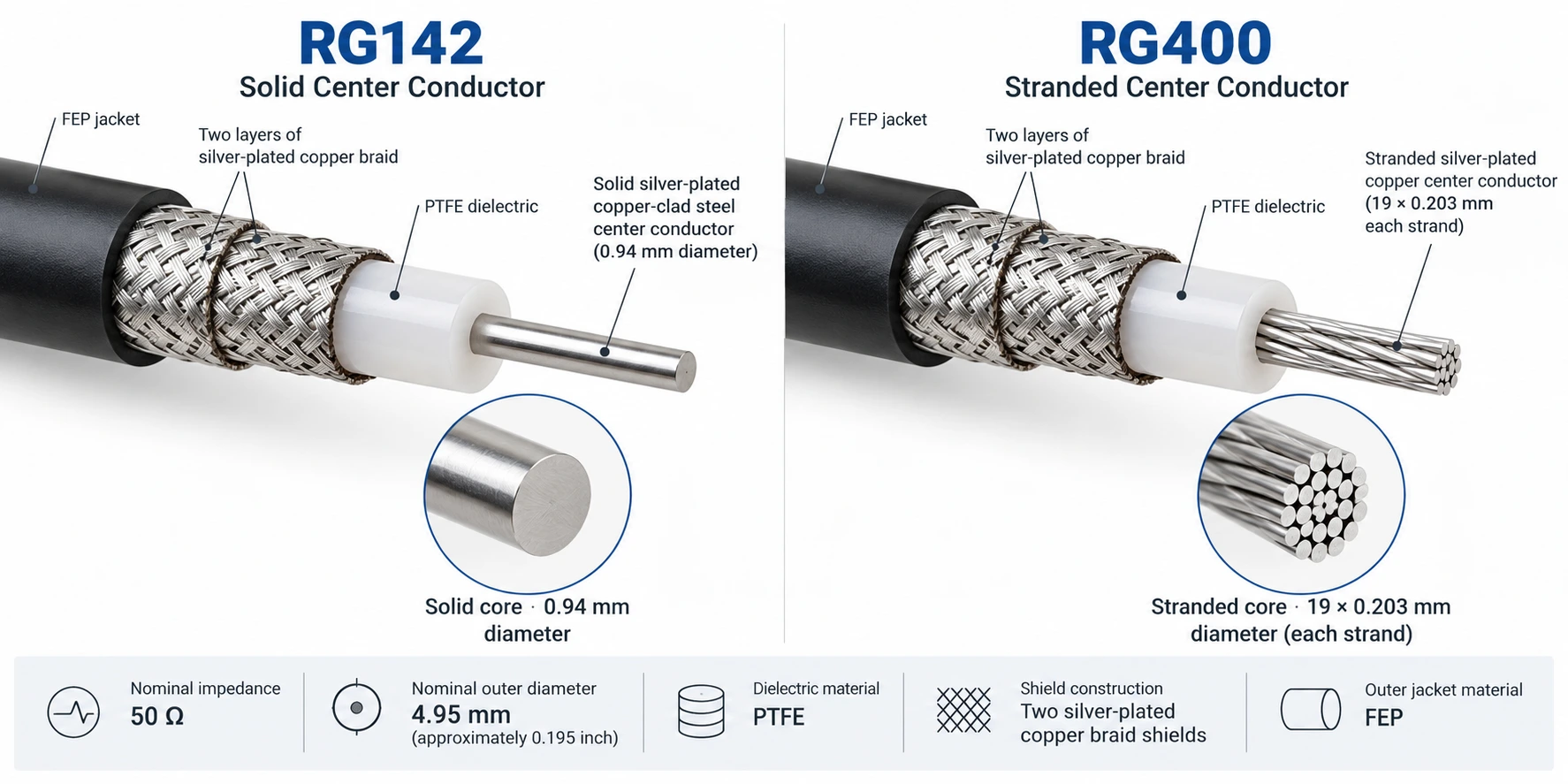
Our RG142 and RG400 cables share several dimensions and materials. Their center conductors are the starting point for choosing between them.
| Comparison | Hongsen RG142 | Hongsen RG400 | What it means for your design |
|---|---|---|---|
| Center conductor | Solid silver-plated copper-clad steel | Stranded silver-plated copper | Different conductor materials and structures require separate electrical and termination checks |
| Conductor size | 0.94 mm diameter | 19 strands of 0.203 mm each | Confirm the center contact fits the actual conductor; 0.203 mm is the individual strand diameter |
| Routing and handling | Stiffer solid conductor | Generally more flexible stranded conductor | Start with RG400 when positioning the cable around components is a priority |
| Termination preparation | Prepare a solid center wire | Keep the conductor strands intact during preparation | Follow the connector's cable-specific stripping and contact instructions |
What they have in common: both Hongsen constructions have 50-ohm nominal impedance, PTFE insulation, two silver-plated copper braid shields, an FEP jacket and a nominal overall diameter of 4.95 mm, approximately 0.195 inch.
These shared features explain why the cables are often considered for similar RF connections. They do not make the two cables automatically interchangeable. You can view the full construction details for our RG142 cable and RG400 cable.
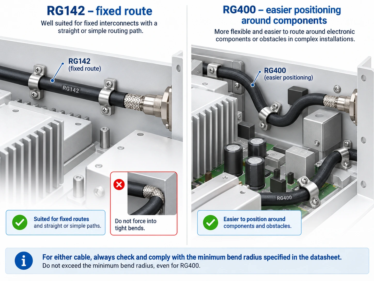
RG400's stranded center conductor generally makes it easier to position during assembly. This can be useful when a connection must follow a route around components or reach a connector at an awkward angle.
RG142: a suitable candidate for a fixed route where the cable can be installed without forcing it into a tight bend.
RG400: a useful starting point when easier handling and positioning are important to the installation.
For either cable, check the permitted bend radius. Greater flexibility does not establish a smaller approved radius or a continuous flexing capability. If the connection moves during use, include that motion in the selection requirements.
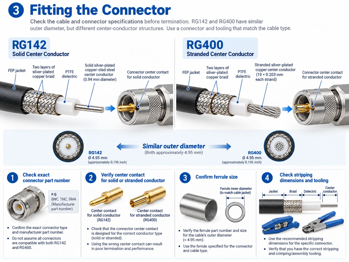
Both cables have the same nominal jacket diameter, but their center conductors differ. Check the termination before reusing a connector or replacing an existing assembly.
Match the exact connector part number to its approved cable types.
Check the center contact and preparation method for a solid or stranded conductor.
Confirm the ferrule size, stripping dimensions and assembly tooling.
An SMA or BNC interface describes how connectors mate. The cable termination still needs to fit the chosen RG142 or RG400 construction.
Mechanical flexibility gives RG400 a handling advantage. Electrical performance requires a separate comparison. We recommend matching the offered cable specifications to the actual connection rather than assuming either RG type always has lower loss or higher power capacity.
| Requirement | Compare RG142 and RG400 on this basis | Why it affects the choice |
|---|---|---|
| Signal loss | Attenuation at the same operating frequency, cable length and temperature | A small difference per metre becomes more significant over a longer run |
| RF power | The applicable power rating at your frequency and ambient temperature, including connector limits | A voltage rating alone does not establish the RF power capacity of the finished connection |
| Operating environment | The specified temperature range and installation conditions of each offered cable | Shared PTFE and FEP materials do not establish identical ratings for every construction |
For a short internal connection, routing and connector fit may be the deciding factors once both cables meet the electrical requirements. For a longer run or a tight loss budget, compare attenuation first, then check whether either cable leaves enough margin for the connectors and the rest of the RF path.
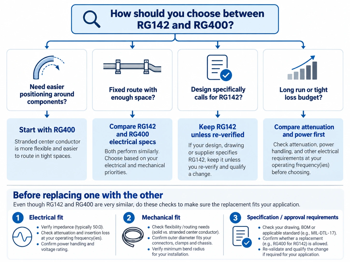
Use the installation requirements to narrow the choice, then confirm the electrical specifications.
| Your situation | Start with | Reason |
|---|---|---|
| A fixed interconnect with enough routing space | RG142 or RG400 | Either may fit; compare the specified electrical performance and the existing design requirements |
| A route that needs easier positioning around components | RG400 | The stranded center conductor generally makes handling easier |
| An approved design that specifically calls for RG142 | The specified RG142 construction | Replacing it with RG400 requires checking the design and termination requirements |
| A long cable run or a demanding RF loss budget | A loss comparison before selecting either | Length and frequency may make a different cable construction more appropriate |
The practical choice: consider RG400 when handling is the main challenge. Keep RG142 in consideration for fixed connections, especially where the design specifies a solid conductor. When loss or power is the limiting factor, let the application-specific electrical comparison decide.
RG400 may be a suitable alternative, but matching 50-ohm impedance and 4.95 mm overall diameter is only the first check. Review the proposed replacement in three steps:
Confirm electrical fit. Compare attenuation, operating frequency and the required power rating at the intended cable length and temperature.
Confirm mechanical fit. Check the routing space, bend radius and compatibility of the connector termination with the stranded conductor.
Confirm purchasing requirements. Check the exact cable specification, documentation and any approval requirements in the original design.
The same process applies when replacing RG400 with RG142. The replacement must work as a complete connection, including its terminations.
Generally, yes. Its stranded center conductor makes routing and positioning easier. Check the specified bend radius and motion requirements separately.
Our listed constructions both use two silver-plated copper braid shields. Shield count therefore gives no basis for choosing one over the other. Where RF isolation is critical, compare the required shielding performance and the connector termination.
No. The RG142 construction described here has braided shields. A solid center conductor does not make it semi-rigid; semi-rigid coaxial cable uses a solid tubular outer conductor.
If easier routing is your priority, take a closer look at our RG400. If your fixed connection calls for a solid center conductor, our RG142 is a starting point. Both are available in our RG MIL-C-17 coax cable range.
Still deciding between the two? Send us your connection requirements—your operating frequency, cable length and connector details are a useful place to start. Include a drawing if the route is tight. We can help you compare the available constructions against your electrical and installation needs.